From Rungs to Wrenches
Comprehensive Guide for Taming Two-Ram Balers, Compactors, and Other Industrial Monstrosities
Written by Soapstone

“Clean hands are lyin’ hands” - Paul Whitman
Foreward:
This is a compilation of the thoughts that go through my head while I'm sitting in my truck pretending to fill out work orders. Nobody cares what we actually do, they just want it fixed so the numbers will go parabolic approaching infinity. This is a thankless and underpaid job, but maybe one day that will change and maybe our industry will be redeemed from obscurity.
Introduction
Congratulations on your new role as custodian of a decades-old industrial machine that can crush both bone and stone with equal enthusiasm, while being the most temperamental piece of machinery you'll ever encounter. Why are you reading this? Because your predecessor either:
-
Quit in frustration after the third hydraulic explosion
-
Disappeared mysteriously during the night shift (check the last bale)
-
Was promoted after mastering the dark arts contained in this guide
Know this: your two-ram baler/compactor is both your nemesis and, potentially, your greatest ally in the war against waste. It will fight you every step of the way. It will withhold its secrets. It will make sounds that haunt your dreams. And yet, with this guide, you might—just might—survive long enough to pass this knowledge on to the next poor soul. Before you press a single button, understand what you're dealing with. Your two-ram baler is essentially a hydraulically-powered mechanical dinosaur with the temperament of a cat that's been bathed against its will. You’ll find yourself crawling through the bowels of the baler, flashlight in hand, searching for that elusive problem. It’s a rite of passage, a test of your resolve, and if you come out the other side with all your fingers intact, you’ll wear that victory like a badge of honor.
The first part of this detailed guide outlines how a PLC programmer would approach a basic two-ram baler or other automated industrial system, focusing on Allen Bradley parts(primarily MicroLogix 1400 and RSLogix 500), while emphasizing the importance of each component for safety and functionality. The process begins with power setup and extends to integrating sensors and safety features, ensuring a robust control system. Please be aware that this guide consistently references Allen Bradley’s absurdly expensive software, but the fundamental concepts are relevant for any diagnosing or troubleshooting adventure. Ladder logic is one of five standardized ways to program PLCs and ladder logic is by far the most common method. If your goal is to learn the fundamentals, reach out to me and I’ll send you a basic ladder logic editor with a basic PLC simulator. This will allow you to write programs and set parameters while observing the results. Reading, like YouTube videos, should be a supplement to your training and not the main source of experience. With that being said, let’s lay the foundation. The first step is turning on the PLC. This guide is for the guy who’s ready to step up from wrench-turning to mastering the art of the Automation Technician. Nothing exposes a technician’s limits like the Fluoride Stare when asked to connect to a PLC, and the key to avoiding that is nailing the setup. Using Allen Bradley’s MicroLogix 1400 with RSLogix 500 and RSLinx Classic, this guide dives into finding the right protocol, configuring drivers, and tackling issues that will inevitably morph from “easy hours” into raw and unfiltered moments where you question your career decisions.
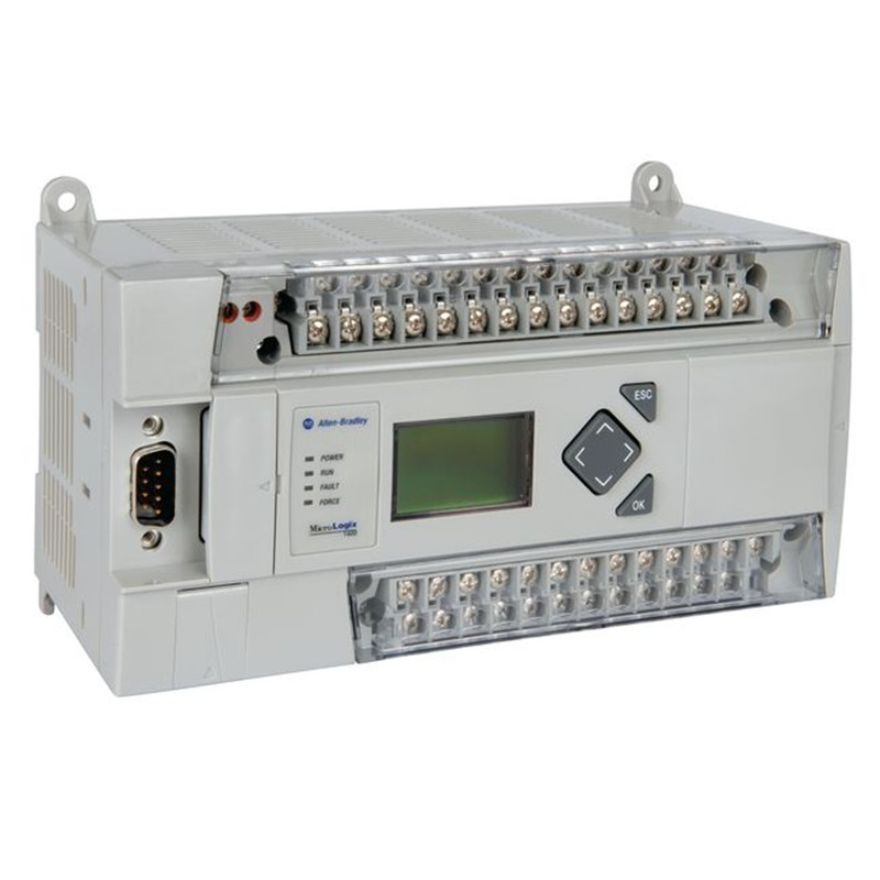
We will start from the Genesis of every service call: does the PLC have power?
Electrical Setup and Power Supply
Nearly every industrial control system I’ve worked on operates on a three-phase 480V AC supply, common in industrial settings. A control transformer usually steps this down to 120V AC, which is needed for safely and efficiently powering the control circuit. The control circuit includes the PLC, input devices (e.g., buttons, sensors), and output devices (e.g., contactors, solenoids). For an Allen Bradley PLC, such as the MicroLogix 1400, this voltage, 120V AC, can directly power the unit. Some control circuits will utilize 24V DC. If your PLC is rated for 24V DC, ensure an appropriate power supply is installed after the control transformer and before the PLC(e.g., 1606). Reducing line voltage is crucial for safety, as it isolates high-voltage components from control signals, reducing risk to operators. Now we have taken our supplied voltage and turned it into something safe and usable. We can power our PLC and discuss how we get power to the motor. Remember, we are separating low-voltage devices like the PLC from the high-voltage devices such as a 480v motor, so we need a middleman to handle some of the heavy lifting. This is the genius behind control systems, both electrical and hydraulic. In electricity, we use a pilot voltage to trigger a high-voltage switch, that way we don’t have to actually touch the high voltage. In hydraulic systems, we use a pilot pressure to shift valves that channel oil into one place or another without needing massive and costly valves. This is like having a really long fuse on a stick of dynamite. It creates space between the dangerous parts so that you can hide high voltage in a cabinet and high pressure inside a manifold. Even something very powerful can be made safe if you plan in advance.
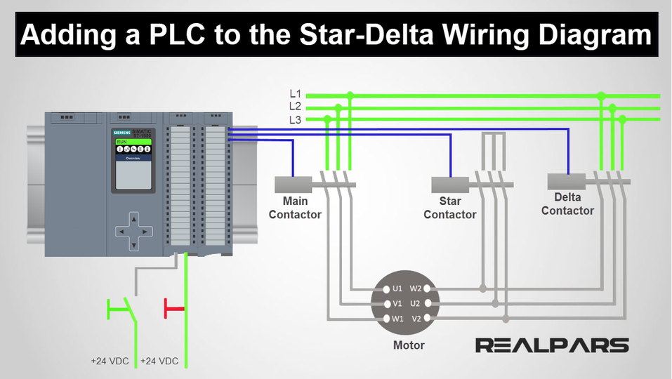
Motor Control and Contactor Operation
The motor, driving a hydraulic pump, is controlled via a contactor, such as an Allen Bradley 100-C series. This is our middleman between the PLC and the motor. The PLC will have a wire connected to the motor contactor coil. The motor contactor coil is literally a giant coil of wire that turns into a big magnet. When the coil has enough energy, the magnet will be strong enough to overcome the force of the spring that usually keeps it open. When the spring can’t keep the two sides separate anymore due to the strength of the magnetic field from the coil/core, the copper from the line side 480v comes into contact with the copper on the 3 motor-side leads. When the copper makes contact, it closes the circuit like a drawbridge and allows voltage to pass through the contactor and into the overload, and finally out to start the motor. An overload relay(e.g., 193-E series), monitors current going to the motor to protect against overcurrent, with normally closed contacts in series with the contactor coil. If tripped, it de-energizes the contactor coil, stopping the motor, and the PLC can read an auxiliary contact for status. Amperage overdraw is a common issue with older motors and there are loads of great resources online that explain motor troubleshooting in detail. More importantly, a good technician should have a strong grasp on the fundamentals of electrical principles. Understanding how an overload works is a great start. You might read normal line-to-line or line-to-ground voltage when diagnosing a bad motor but that doesn’t mean there’s nothing wrong. Picture the motor spinning freely and then a scrapyard robot comes to life and grabs the shaft of the spinning motor. The motor is going to try to speed back up to full speed, but the resistance from the deathgrip of the robot is forcing the motor to run below desired speeds. The motor is going to try to draw more power (request more torque), but the voltage is not going to change because it’s set to a certain amount by the physical transformer configuration established by the electricity provider. As long as you don’t have a fault or short in your motor windings, the impedance of an AC motor really won’t ever change much. This is an extremely important concept that can help alleviate many of the headaches you’ll face when hunting down electrical problems, so I’ll recap before we move on:
The voltage (( V )) supplied to the motor is fixed by the power source (e.g., 480V in an industrial system). When the motor experiences a mechanical load (like the robot grabbing the motor shaft), the motor slows down, reducing its back-EMF (a voltage generated by the motor’s rotation that opposes the supply voltage). This reduction in back-EMF allows more current to flow through the motor’s windings, but the supply voltage stays the same because it’s controlled externally by the power system, not the motor’s internal behavior.
Resistance (( R )) Stays Roughly Constant:
The resistance (or more accurately, impedance in an AC motor) of the motor’s windings is a physical property of the motor’s design and doesn’t change significantly with load. While temperature increases from higher current could slightly increase resistance, this effect is minimal in the short term and not the primary factor here. The motor’s stator winding impedance (( Z ), which includes resistance and inductive reactance) remains relatively constant, though we simplify it as resistance (( R )).
Why Current (( I )) Increases:
When the motor is loaded and slows down, it demands more torque to try to return to its normal speed. To produce more torque, it draws more current. However, in a motor, the "effective voltage" driving current is influenced by the difference between the supply voltage and the back-EMF. As back-EMF drops under load, the effective voltage across the windings increases slightly, causing a significant increase in current without changing the supply voltage or resistance. When this current spikes, you want to make sure your safety devices are set properly to prevent loss of power or… worse… you might have to buy some new parts which means your boss isn’t getting that shiny new truck until next year. Good luck learning Spanish, Mijo. In the meantime, I’ll do my best to help you learn to prevent any critical failures. We can start with how to correctly set your overload.
Ensure your overload is set correctly by first finding your motor’s FLA, or full-load current, Amperage, Amps, etc. If your motor is variably high OR low voltage, ensure you are using the correct amperage. For example, the photo shows VOLTS 208-230/460
AMPS 21-18.8/9.4. This means that if your nominal motor voltage is set up for 230v power, your AMPS will be 18.8. If you’re connecting a 460V system, you’re going to use 9.4 as your FLA number for the sake of setting the overload. Check your OWN motor’s numbers.
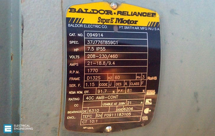
Next, you’ll need to find your motor’s SF, or service factor. The service factor is a multiplier indicating how much overload the motor can handle for a short period. In the example photo, this motor’s SF is 1.15. This is a percentage; the motor is telling us that it can run at 1.15x FLA (1.15x more amp draw than normal) for a short time without an issue. We can multiply our FLA or max amps and our SF to determine the maximum allowable current for the overload relay. In our example, our Amps (FLA) = 18.8 and our SF = 1.15.
18.8 amps × 1.15 SF = 21.62 Amps. This is our magic number, and this number tells us that our motor can safely operate at a maximum of 21.62 amps, but only for a short time before it needs to return to normal draw to prevent damage or overheating. Finally, Set the Overload Relay. Most overload relays have a dial or knob that allows you to adjust the current setting. Set the dial to the calculated maximum allowable overload rating (e.g., 21.62 amps in the previous example).
Consider the motor runs a hydraulic pump and the oil is too cold. The pump has trouble moving the oil which causes resistance. The motor tries to spin the pump anyways but it struggles, increasing the amperage draw. As long as it doesn’t spike above our number and as long as it isn’t sustained at this stress level, the motor will handle it. Remember that overload relays will trip when the motor exceeds its set rating for a period of time, not instantaneously. This is designed this way to allow for short bursts of higher current, like a motor starting or brief load and demand increases. If your overload is tripping tripping, it will require someone to manually push the reset button and diagnose the issue.
DISCLAIMER!:
RTFM!!! Make sure the overload relay is set to the correct setting for the motor's FLA and service factor by checking the manufacturer’s data. Do not ever assume something looks similar and don’t assume something will work. Most of this hardware is expensive and often obsolete. The best technicians in the world will make mistakes. Try to keep the mistakes cheap.
Power to the PLCple
The PLC is the brain of your system, but it’s basically just a black box of voodoo mystery without a proper introduction. The operator presses the Start button which allows control voltage (120V or 24V) to reach its respective PLC Input. The PLC is programmed to listen on a certain screw terminal and wait for voltage. When the PLC recognizes that the full control voltage is hitting an input terminal, the PLC output module - a relay output that’s programmed to handle this task, energizes a specific output terminal. PLC programming is telling the PLC, “Hey computer, when you see 120V hit the 1st input screw, I want you to send 120V out of the first output screw”. You can increase the complexity of the system infinitely, but always follow KISS. Otherwise, you’re going to KISS your ass goodbye when you’re the only person who’s able to fix your program so you’re the lucky winner of frequent trips to somewhere you really don’t want to be.
Rule(s) of thumb:
>Inputs should always be labeled with the first character being I(e.g., I:1/0 might be MOTOR START, which tells the PLC that the operator pressed the start button. Many times this will look like the number ONE but don’t be fooled, there should be no labels with the first character being ONE going into the PLC inputs).
>Outputs should always be labeled with the first character being O(e.g., O:1/1 might be the relay that sends voltage to turn a light on when certain input parameters are met. For instance, if the operator clicks the START button, you might want to send voltage out to a warning horn and a warning light so that nearby personnel are aware of the hazard)
Understanding the PLC and Communications Protocols
We need a PLC connection to your laptop. Protocols are the language your computer uses to talk to the PLC, and choosing the wrong one is like trying to order coffee in Pig Latin.
Common protocols for Allen Bradley PLCs include:
-
DF1: A serial-based protocol, often used with RS-232 cables for point-to-point connections.
-
DH-485: A multi-drop protocol for older Allen Bradley networks, requiring specific cables like a 1747-UIC converter.
-
Ethernet/IP: A modern, network-based protocol for PLCs with Ethernet ports, like the MicroLogix 1400’s built-in port.
-
DeviceNet or ControlNet: Less common for basic setups, used in complex systems with multiple devices. Easier to monitor, harder to implement and repair.
You must match the protocol to the PLC’s hardware and the physical connection (e.g., serial cable, Ethernet cable). A mismatch means no connection, and hours wasted staring at error messages. I’ve replaced entire racks just to learn that my cable was bad. Don’t be like me. Inspect the PLC’s ports and your laptop’s capabilities. For a MicroLogix 1400, check for an Ethernet port (RJ45) or serial port (8-pin mini-DIN). If using Ethernet, Ethernet/IP is likely your protocol. For serial, DF1 is the go-to. Refer to the PLC’s manual to confirm supported protocols. Seek wisdom from the elders if you need more information on which cable to use (Read the fkn manual, seriously).

Alright, I won't leave you hanging. This is where 99% of people are going to give up. There is no easy way to explain this to someone who's new with technology, but you are going to experience issues that aren't listed here. You're going to have problems that you don't understand and you're going to spend countless hours trying to figure out what the problem is. You will find nothing online, and what little you stumble across will be a decade old post from another lost soul screaming into the void on StackOverflow, begging for some relief from the ailment you both share. My goal is to compile the bits of knowledge that I've found during my own quests. Perhaps this will help you one day, and perhaps it won't, but many people will parrot terminology without actually knowing what it means. This is certainly a "fake it til you make it" kind of industry, but I simply wasn't able to accept that things just work because magic. Quite frankly, most of the stuff that I work with sucks and my first thought is often, "there's definitely a better way to do this and I'm going to list 10 of them to the person responsible for it". Terrible strategy if you're trying to keep your boss happy.
Anyways, I want to elaborate on these protocols. What are they, and why do we use them? What is actually happening INSIDE the copper? Can we just tape a cable back together if it gets pinched in the MCC door? If so, which ones? Do you know how to punch out an RJ45? Do you know which of the two configurations you would use, or are you going to go rogue and support 3rd party conventions? A few of these will be left up to discovery. This data is directly from the data references and is intended to give you an idea of how they work. We aren't in the business of repairing cables, but knowing the difference between the protocols helps.
1. Serial-Based Protocols (e.g., RS-232, UART)
Physical Setup:
-
Wires: Typically involves a cable with at least two data lines (e.g., TX for transmit, RX for receive) and a ground (GND). For RS-232, a DB-9 connector is common.
-
Pins: Key pins include TX (transmit data), RX (receive data), and GND. RS-232 may also use control pins like RTS (Request to Send) and CTS (Clear to Send) for flow control.
-
Example: A computer (DTE) connected to a modem (DCE) via an RS-232 cable.
What Happens Physically:
-
Voltage Levels:
-
RS-232 uses bipolar signaling: a logical "1" (mark) is represented by a negative voltage (-3V to -15V), and a logical "0" (space) is a positive voltage (+3V to +15V).
-
UART (a simpler serial protocol) uses TTL levels: 0V for "0" and 3.3V/5V for "1".
-
Signal Flow:
-
The TX pin of the sender generates voltage pulses corresponding to bits. For example, to send a byte (e.g., 01000001 for ASCII 'A'), the TX pin toggles between high and low voltages in sequence, following a start bit, data bits, optional parity, and stop bit(s).
-
The RX pin of the receiver detects these voltage changes and reconstructs the bit sequence.
-
Ground provides a common reference to ensure accurate voltage interpretation.
-
Timing:
-
Bits are sent at a fixed baud rate (e.g., 9600 bps). Each bit occupies a time slot (e.g., ~104µs at 9600 baud).
-
No clock signal is transmitted; the receiver synchronizes using start/stop bits.
-
Example:
-
Sending 'A' (01000001) at 9600 baud over RS-232: The TX pin starts at -12V (idle), drops to +12V for the start bit, toggles between ±12V for each bit (e.g., +12V for 0, -12V for 1), and returns to -12V for the stop bit. The RX pin sees these transitions and decodes them.
-
Physical Behavior:
-
The wire carries a continuous stream of voltage pulses. Only one device transmits at a time per wire (TX to RX is unidirectional).
-
Noise or long cables can distort signals, requiring careful shielding or shorter distances (e.g., RS-232 max ~15m at 9600 baud).
Key Physical Trait: Single, point-to-point voltage transitions with no shared bus contention.
2. Multi-Drop Protocols (e.g., RS-485, CAN, DH485)
Physical Setup:
-
Wires: Uses a shared bus, typically a twisted-pair cable for differential signaling (e.g., A and B lines for RS-485, CAN-H and CAN-L for CAN) plus a ground reference.
-
Pins: Devices connect to the bus via A/B pins (RS-485) or CAN-H/CAN-L pins (CAN). Termination resistors (e.g., 120Ω) are often added at bus ends to prevent signal reflections.
-
Example: An industrial PLC (master) polling multiple sensors (slaves) on an RS-485 bus.
What Happens Physically:
-
Voltage Levels:
-
RS-485: Uses differential signaling. Logical "1" is when V_A - V_B > +200mV (e.g., A = 3.5V, B = 1.5V), and "0" is when V_A - V_B < -200mV (e.g., A = 1.5V, B = 3.5V). Idle state is typically A > B.
-
CAN: Also differential. Dominant state ("0") is when CAN-H - CAN-L ≈ 2V (e.g., CAN-H = 3.5V, CAN-L = 1.5V), recessive state ("1") is when CAN-H ≈ CAN-L ≈ 2.5V.
-
Signal Flow:
-
RS-485:
-
All devices share the bus. The master’s transmitter drives the A/B lines to create differential voltage pulses for each bit.
-
For example, to send a Modbus RTU frame, the master’s TX pins toggle A/B voltages (e.g., A high, B low for "1") per bit. Slaves’ RX pins detect the differential voltage to decode bits.
-
Only one device transmits at a time (half-duplex); others keep their transmitters off (high-impedance state) to avoid bus conflicts.
-
Slaves respond when addressed, driving the bus similarly.
-
CAN:
-
Any node can initiate transmission. Nodes drive the bus to a dominant (0) or recessive (1) state.
-
If multiple nodes transmit, CAN’s arbitration ensures the highest-priority message (lowest ID) wins without collision. A node sending a recessive bit but seeing a dominant bit backs off.
-
For example, sending a CAN frame: The TX pins of a node toggle CAN-H/CAN-L to encode bits (e.g., dominant for 0, recessive for 1). Receivers detect these states.
-
Timing:
-
RS-485 relies on a baud rate (e.g., 19200 bps) with start/stop bits for synchronization, like serial.
-
CAN uses a bit rate (e.g., 1 Mbps) with a shared clock derived from bit edges and stuff bits to maintain sync.
-
Example:
-
RS-485: Master sends a Modbus query (e.g., slave ID 1, read register). The A/B lines toggle differentially (e.g., +2V to -2V) for each bit. The addressed slave responds, driving A/B similarly.
-
CAN: A sensor sends a data frame (e.g., temperature). CAN-H/CAN-L toggle between 2V differential (dominant) and ~0V (recessive) per bit. Other nodes monitor and acknowledge.
-
Physical Behavior:
-
The bus sees differential voltage swings driven by the active transmitter. All devices monitor the bus, but only one drives it at a time (RS-485) or arbitration resolves conflicts (CAN).
-
Differential signaling reduces noise, enabling longer distances (e.g., RS-485 up to 1200m, CAN up to 40m at 1 Mbps).
-
Termination resistors absorb reflections on long buses.
Key Physical Trait: Shared bus with differential signaling, requiring strict control to avoid collisions (RS-485) or arbitration (CAN).
The DH-485 protocol, developed by Allen-Bradley (Rockwell Automation), is a multi-drop protocol used primarily for communication between programmable logic controllers (PLCs), HMIs, and other industrial devices in small to medium-scale automation systems. DH-485 operates as a multi-drop protocol over the RS-485 physical layer in most implementations, so its physical behavior is similar to RS-485 multi-drop, with specific protocol-driven nuances. Here’s a detailed look:
-
Voltage Levels:
-
DH-485 uses differential signaling per the RS-485 standard. The A and B lines carry complementary voltage signals:
-
Logical 1 (mark): V_A - V_B > +200mV (e.g., A = 3.5V, B = 1.5V).
-
Logical 0 (space): V_A - V_B < -200mV (e.g., A = 1.5V, B = 3.5V).
-
Idle state: Typically, A > B (small positive differential, e.g., +200mV), though this depends on the network’s bias resistors.
-
Voltage swings are usually within 1.5V to 5V per line, relative to the common ground, driven by the RS-485 transceiver (e.g., a 5V supply).
-
For DH-485 over RS-232 (rare), it uses single-ended signaling with voltages like RS-232 (±3V to ±15V for mark/space), but this is not multi-drop and limited to specific devices (e.g., ControlLogix CH0 port).
-
Token-Passing Mechanism: DH-485 uses a token-passing protocol to manage bus access, ensuring collision-free communication. Only the device holding the token can transmit, making it a deterministic multi-drop system.
-
When a device has the token, its RS-485 transceiver’s transmitter pins (connected to A and B) drive differential voltage pulses onto the bus to encode a DH-485 message (e.g., a read/write command to a PLC’s data file).
-
For example, to send a message like a PLC data read request, the transmitter toggles A and B voltages (e.g., A high/B low for "1", A low/B high for "0") for each bit in the frame, which includes headers, node addresses, data, and error-checking (e.g., CRC).
-
All other devices on the bus keep their transmitters in a high-impedance state (off), allowing their receiver pins (also connected to A/B) to monitor the bus and decode the differential signals.
-
Message Structure: A typical DH-485 frame includes:
-
Destination Node Address (0–31, identifying the target device).
-
Source Node Address (identifying the sender).
-
Command/Data (e.g., read/write PLC registers).
-
Error Checking (proprietary CRC or checksum).
-
The frame is encoded as a series of bits, with each bit represented by a differential voltage transition on A/B.
-
Receivers: Every device’s RS-485 receiver continuously monitors A/B lines. If a message’s destination address matches a device’s node ID, it processes the message and may respond (when it gets the token). Otherwise, it ignores the data.
-
Token Passing: After transmitting, the device passes the token to the next node by sending a token frame. This frame’s bits are similarly encoded as differential pulses on A/B. The process repeats, cycling through all nodes.
-
Timing:
-
DH-485 operates at fixed baud rates, typically 9600 or 19200 bps (sometimes up to 57.6 kbps in specific setups).
-
At 19200 baud, each bit lasts ~52µs. A frame (e.g., 20 bytes) takes ~8.3ms to transmit, excluding token overhead.
-
Synchronization relies on start/stop bits per byte, like standard serial communication. No separate clock line exists; devices align to bit edges.
-
Token rotation time depends on the number of nodes and message frequency, ensuring predictable communication cycles.
-
Example:
-
Suppose an SLC-500 PLC (node 1) sends a read request to a PanelView (node 2):
-
The PLC’s 1747-AIC module, holding the token, drives the A/B lines. For a byte like 0x41 (01000001), it sends a start bit (A low/B high), followed by eight bits (toggling A/B per bit), and a stop bit (A high/B low).
-
Voltages might swing like: Start bit (A=1.5V, B=3.5V), bit 0 (A=3.5V, B=1.5V), bit 1 (A=1.5V, B=3.5V), etc.
-
All nodes see this, but only node 2 processes it. When node 2 gets the token, it responds similarly, driving A/B to send data back.
-
After transmission, the PLC passes the token to node 2 or the next node, encoded as another differential signal sequence.
-
The bus remains idle (small positive differential) between transmissions, with bias resistors maintaining stability.
-
Physical Behavior:
-
The A/B lines carry rapid differential voltage swings for each bit, driven by the active node’s transmitter. All nodes share the same pair, so only one transmitter is active at a time, enforced by token passing.
-
Termination resistors (120Ω at each end) absorb reflections, critical for long cables (up to 4000ft) at 19200 baud, preventing signal distortion.
-
Shielding and twisted pairs reduce electromagnetic interference (EMI) from motors or other industrial noise sources, ensuring reliable signal detection.
-
The common pin provides a ground reference, stabilizing the differential signals across devices with potentially different ground potentials.
-
If DH-485 runs over RS-232 (e.g., via a 1761-NET-AIC converter), the TX/RX pins use single-ended voltages (±5V to ±15V), but this is point-to-point, not multi-drop, with one device’s TX pin driving the other’s RX pin.
-
Differences from Generic RS-485:
-
While RS-485 defines only the electrical layer, DH-485 adds a proprietary data-link layer (token-passing, addressing, error-checking). Physically, the A/B lines behave like standard RS-485, but the signal patterns reflect DH-485’s frame format and token protocol.
-
Unlike Modbus RTU (another RS-485 protocol), which uses master-slave polling, DH-485’s token-passing allows peer-to-peer communication, affecting how devices drive the bus.
Comparison to Other Protocols
-
Serial-Based (e.g., RS-232):
-
DH-485 over RS-485 uses differential signaling vs. RS-232’s single-ended, enabling longer distances (4000ft vs. 50ft) and multi-drop (32 nodes vs. point-to-point).
-
RS-232’s TX/RX pins are dedicated; DH-485’s A/B pins are shared, with token passing managing access.
-
Multi-Drop (e.g., Generic RS-485, CAN):
-
Like RS-485-based Modbus, DH-485 uses A/B differential lines, but its token-passing avoids collisions, unlike Modbus’s master-slave contention.
-
Compared to CAN, DH-485 is slower (19200 bps vs. 1 Mbps) and uses simpler arbitration (token vs. CAN’s bit-wise dominance), but both share a bus with differential signaling.
-
Network-Based (e.g., Ethernet):
-
DH-485’s single shared bus (A/B) is slower and less scalable than Ethernet’s dedicated TX/RX pairs (100Mbps+). Ethernet uses complex encoding (e.g., MLT-3), while DH-485’s raw bit pulses are simpler.
-
Ethernet’s full-duplex eliminates contention; DH-485’s half-duplex bus relies on tokens, limiting throughput.
Key Physical Traits
-
Wires/Pins: Two-wire (A/B) differential bus via RS-485, with A/B pins on terminal blocks (e.g., 1747-AIC) driving/receiving signals. Rarely, RS-232 TX/RX for point-to-point.
-
Signal: Differential voltages (~±200mV to ±2V) encode bits, with one node at a time driving the bus, controlled by token frames.
-
Behavior: Token-passing ensures orderly A/B transitions, with all nodes monitoring but only the token-holder transmitting. Long cables and noise immunity are enabled by differential signaling and shielding.
Notes
-
Proprietary Nature: DH-485’s token-passing and frame details are proprietary, unlike open RS-485 protocols (e.g., Modbus). Exact frame formats (beyond PCCC commands shared with DF1) are not fully public, complicating custom implementations.
-
Legacy Status: DH-485 is considered legacy, with modern systems favoring Ethernet/IP, but it’s still used in existing Allen-Bradley SLC-500/MicroLogix setups due to reliability.
-
Example Hardware: A typical DH-485 network might include an SLC-5/03 PLC, a 1747-AIC coupler, and a PanelView, all daisy-chained via Belden 9842 cable, with A/B pins connected across devices.
If you need a waveform diagram, specific pinout (locator) for a device like the 1747-AIC, or details on DH-485’s software layer, let me know, and I can dig deeper!
3. Network-Based Protocols (e.g., Ethernet, TCP/IP)
Physical Setup:
-
Wires: Typically uses twisted-pair cables (e.g., Cat5e with four pairs for Ethernet) or fiber optics. For twisted-pair, two pairs are used for 100Mbps (TX+, TX-, RX+, RX-), four for 1Gbps.
-
Pins: RJ45 connectors with pins assigned for TX and RX pairs (e.g., pins 1/2 for TX+, TX-, 3/6 for RX+, RX- in 100Base-T).
-
Example: A computer sending data to a server over an Ethernet LAN.
What Happens Physically:
-
Voltage Levels:
-
Ethernet (e.g., 100Base-TX) uses differential signaling with MLT-3 encoding. Voltage levels are typically ±1V or ±2V across TX/RX pairs.
-
For 100Mbps, signals toggle at 125 MHz but encode data with three levels (-1V, 0V, +1V) to reduce effective frequency.
-
Gigabit Ethernet (1000Base-T) uses all four pairs bidirectionally with PAM-5 encoding (five voltage levels, e.g., -2V, -1V, 0V, +1V, +2V).
-
Signal Flow:
-
Data is sent in packets (e.g., Ethernet frames). The sender’s TX pins drive differential voltage pulses across TX+/TX- pairs to encode bits.
-
For example, to send an IP packet, the Ethernet PHY chip converts the frame’s bits into MLT-3 (100Mbps) or PAM-5 (1Gbps) signals. The TX pair’s voltage toggles rapidly (e.g., +1V to -1V) per symbol.
-
The receiver’s RX pins detect these differential signals, decoding them back to bits.
-
In full-duplex Ethernet, TX and RX pairs operate simultaneously (no collisions).
-
Switches or routers forward signals by regenerating them on other ports.
-
Timing:
-
Ethernet uses a clock signal (e.g., 125 MHz for 100Base-TX) embedded in the data stream. Preambles and encoding ensure synchronization.
-
Precise timing allows high speeds (100Mbps, 1Gbps, or higher).
-
Example:
-
Sending a TCP packet over 100Base-TX: The NIC’s TX pins drive TX+/TX- with MLT-3 signals (e.g., +1V, 0V, -1V transitions) for the frame’s bits (preamble, destination MAC, data, CRC). The switch’s RX pins decode this, and its TX pins forward it to the destination.
-
Physical Behavior:
-
Each twisted pair carries rapid differential voltage swings encoding symbols, not raw bits. For 100Base-TX, MLT-3 reduces signal frequency to fit cable bandwidth.
-
Full-duplex allows simultaneous TX/RX on separate pairs, eliminating collisions.
-
Long distances (e.g., 100m for Cat5e) are supported due to robust encoding and noise rejection.
-
Transformers in Ethernet ports isolate devices, preventing ground loops.
Key Physical Trait: High-speed, differential, packet-based signaling over dedicated pairs, enabling simultaneous bidirectional communication.
You don't have to memorize this stuff, but diagnosing PLC problems is much deeper than knowing how to write interesting logic. (The logic WILL come, and it's the most fun part). The most important thing to remember is that rs-232 and
Setting Up RSLinx
RSLinx is the communication middleware that links RSLogix 500 to your PLC. Think of it as the translator who ensures your laptop and PLC understand each other. The programmer configures RSLinx to use the right driver for the chosen protocol. Some PLCs will have a light on the front (e.g., SLC 5/03, 5/04, etc.), which will indicate the appropriate protocol. I’ll add a link here to a more exhaustive approach in case you’re actually stuck on this.
Step-by-step setup:
-
Launch RSLinx Classic: Open RSLinx Classic (e.g., Lite version, sufficient for programming).
-
Access Communications Setup: Go to “Communications” > “Configure Drivers.” This is where you tell RSLinx how to talk to the PLC.
-
Select the Driver:
-
For Ethernet/IP: Choose “Ethernet devices” or “Ethernet/IP Driver.” You’ll need the PLC’s IP address (e.g., 192.168.1.100). If the PLC is on a network, ensure your laptop is on the same subnet.
-
For DF1: Select “RS-232 DF1 devices.” Specify the COM port (e.g., COM1) and settings like baud rate (default 19200), parity (none), and device type (MicroLogix 1400). To find the COM port, open Device Manager on your operating system and expand the Ports tree. You should see your device.
-
For DH-485: Choose “1747-PIC/AIC+ Driver” if using a serial converter, or a USB-to-DH-485 adapter like 1747-UIC. With the USB adapter, you can simply choose the DH485 UIC driver.
-
Configure Driver Settings:
-
Ethernet: Add the PLC’s IP address in the driver configuration. Use “ping” from Command Prompt to verify connectivity (e.g., ping 192.168.1.100).
-
DF1: Set the COM port to match your cable (e.g., 1761-CBL-PM02 for MicroLogix). Double-check baud rate and node address (default 1 for PLC).
-
DH-485: Set the node address and ensure the converter is powered and connected.
-
Start the Driver: Click “Add New,” name the driver (e.g., “PLC_Ethernet”), and start it. The driver should show “Running” in the status window. If you always work on different machines and you constantly delete your drivers, you’re not required to name them.
-
Verify Connection: Open “RSWho” (Communications > RSWho). Browse the driver to see the PLC. A green icon with the PLC’s name (e.g., “1766-L32BXB”) confirms it’s online.
Taking the PLC Online in RSLogix 500
Once RSLinx sees the PLC, it’s time to connect RSLogix 500:
-
Open RSLogix 500: Launch the software and open your project file (or create a new one).
-
Set Communications Path: Go to “Comms” > “System Comms.” Select the RSLinx driver (e.g., “PLC_Ethernet”). Highlight the PLC in the RSWho browser.
-
Go Online: Click “Online.” RSLogix will connect, showing “Remote Run” or “Remote Program” in the status bar if successful.
-
Verify Status: Check the PLC’s mode. If in “Program,” switch to “Run” after uploading or downloading the program, ensuring ladder logic executes.
Troubleshooting Common Issues
Even the best programmers hit snags. Here’s how to tackle the most common issues:
-
“Server Busy” Error:
Cause: RSLinx is overloaded, often because multiple applications are trying to access it, or the driver is misconfigured.
Fix: Close other PLC-related software (e.g., FactoryTalk). Restart RSLinx. Check Task Manager for stray RSLinx processes and end them. Reconfigure the driver, ensuring no duplicate instances exist. Verify only one RSLinx instance runs. Use “Configure Drivers” to delete unused drivers, reducing conflicts.
-
PLC Not Visible in RSWho:
Cause: Wrong protocol, incorrect IP/COM port, or network issues.
Fix:
-
For Ethernet: Confirm the PLC’s IP and subnet match your laptop’s. Use BOOTP to find or set the IP if unknown.
-
For DF1: Check the cable (e.g., 1761-CBL-PM02) and COM port. Test with a different port or cable.
-
For DH-485: Ensure the converter is powered and node addresses don’t conflict. Also check your cable.
-
Run diagnostics in RSLinx (Diagnostics > Driver Diagnostics) to check for errors. Swap cables or ports to rule out hardware faults.
-
Connection Drops:
-
Cause: Unstable network, loose cables, or PLC power issues.
-
Fix: Secure all connections. For Ethernet, check for network congestion or firewall blocking ports (e.g., 44818 for Ethernet/IP). For serial, ensure no EMI from nearby motors.
-
Use shielded cables (e.g., Belden 9841 for serial) and verify PLC power stability with a multimeter.
-
Wrong PLC Type:
-
Cause: RSLogix project is set for a different PLC model.
-
Fix: In RSLogix, go to “Controller Properties” and set the correct model (e.g., 1766-L32BXB for MicroLogix 1400).
-
Double-check the PLC’s catalog number on the hardware label before creating the project.
-
Baud Rate Mismatch (Serial):
-
Cause: PLC and driver baud rates don’t match.
-
Fix: In RSLinx, set the driver’s baud rate to match the PLC’s (default 19200 for MicroLogix). If unknown, try auto-configure in the DF1 driver settings.
-
Note the PLC’s baud rate from its configuration (accessible offline in RSLogix or via a default program).
Why it matters: Troubleshooting separates technicians from wrench-turners. The programmer must systematically isolate issues, ensuring uptime for the baler. Just because you were on site for a week doesn’t mean you weren’t fast. The next guy would’ve taken twice as long…
Keep a log of settings (IP, COM port, baud rate) for each PLC. Use RSLinx’s “Station Diagnostic” to monitor connection health during setup.
Best Practices for Robust Setup
-
Label Everything: Mark cables, note IP addresses, and document COM ports to avoid confusion.
-
Backup Configurations: Save RSLogix projects regularly. Every time you connect to a PLC, ensure you have a backup of that program. If you do not have a backup in your immediate possession then either create a backup or gamble with your sanity.
-
Check Firmware: Ensure the PLC’s firmware matches RSLogix 500’s version (check Rockwell’s Compatibility Center).
-
Secure Connections: Use static IPs for Ethernet to prevent DHCP conflicts. Lock serial cables to avoid disconnections.
These habits save time and prevent errors, letting the programmer focus on logic rather than fighting connectivity.
Importance
Taking a PLC online is the gateway to programming, monitoring, and troubleshooting. Each step—protocol selection, driver setup, issue resolution—builds a reliable link to the system’s brain:
-
Protocol: Ensures the PLC hears your commands, preventing dead-end connections.
-
Driver: Translates your intent into PLC-speak, critical for real-time control.
-
Troubleshooting: Keeps the system running, proving your worth as a technician.
Following IEEE 802.3 (for Ethernet) and TIA/EIA-232-F (for serial) standards ensures professional, interoperable setups, aligning with industry best practices.
Key Citations that every technician needs to use regularly until memorized:
All industrial systems have their own applications, so we will use a generic Two-ram baler as an example.
Coordinating Movement and Safety with Clarity
This section introduces the core operations of a two-ram baler’s control system, designed to help technicians with some electrical or automation experience take the next step in mastering programmable logic controllers (PLCs). The baler uses an Allen Bradley MicroLogix 1400 PLC and RSLogix 500 software to manage its actions, ensuring safe and efficient performance. Here, we’ll break down how the system controls two key components—a main cylinder for compressing materials and a secondary cylinder for ejecting finished bales—while using sensors, safety devices, and precise programming to keep everything running smoothly.
The Baler’s Key Components
The two-ram baler has two cylinders, each driven by a motor and controlled by the PLC. The main cylinder presses materials into a dense bale, while the secondary cylinder pushes the completed bale out of the machine. To prevent these cylinders from moving at the wrong time and causing collisions, the system relies on photoelectric sensors, such as the Allen Bradley 42EF series. These sensors act like the baler’s eyes, detecting whether each cylinder is fully extended, fully retracted, or at its home position. For example, a sensor might send a signal to the PLC when the main cylinder is fully retracted, letting the system know it’s safe to proceed.
The PLC also monitors temperature using a resistance temperature detector (RTD) connected through an analog input module, like the Allen Bradley 1762-IF4. This sensor keeps an eye on the system’s operating conditions to prevent overheating, which could damage components or halt production. Together, these devices provide the PLC with the information it needs to make smart decisions about when and how to move the cylinders.
How the PLC Sequences Operations
The PLC is the brain of the baler, directing each step of the process to ensure everything happens in the right order. The sequence is designed to be safe, efficient, and collision-free, with clear checks at every stage. Here’s how it works in simple terms:
First, the system confirms that all safety conditions are met, such as closed doors and pressed emergency stop buttons being in their normal state. It also verifies that both cylinders are in their retracted, or “home,” positions using the photoelectric sensors. If everything checks out, the PLC allows the operator to start the process.
Next, the PLC activates the motor, which powers the cylinders, if it’s not already running. The motor is controlled through a contactor, like the Allen Bradley 100-C series, which acts as a heavy-duty switch. Once the motor is on, the PLC signals the main cylinder to extend, compressing the material. It waits for a sensor to confirm the cylinder has reached its fully extended position before moving forward.
After compression, the main cylinder retracts, and the PLC checks again to ensure it’s back at its home position. Only then does the secondary cylinder extend to push out the bale. Once the bale is ejected, the secondary cylinder retracts, and the system returns to its starting state, ready for the next cycle.
To keep track of where it is in this sequence, the PLC uses internal memory flags, often called step bits. Each bit represents a specific stage, like “idle,” “main cylinder extending,” or “ejector cylinder retracting.” The PLC moves from one step to the next only when all conditions for that step are satisfied, ensuring the cylinders don’t clash and the process stays orderly.
Programming the Inputs for Control
For the PLC to work correctly, the technician must configure its inputs to match the behavior of the connected devices. Here’s what that looks like:
The start button is a normally open device, meaning it sends a signal to the PLC only when pressed. This tells the system the operator wants to begin a cycle. The stop button, on the other hand, is normally closed, sending a constant signal when it’s not pressed. If the operator hits stop, the signal drops, and the PLC halts the cycle immediately. Safety inputs, such as those from a safety relay monitoring doors or E-stops, are set up to confirm safe conditions before any movement occurs. If these inputs indicate an unsafe state, the PLC pauses operations to protect personnel and equipment.
To make operation user-friendly, the PLC is programmed to keep the motor running after the start button is released. This is done using a latching mechanism in the software, which holds the motor’s “on” state until a stop command or fault interrupts it. This feature reduces operator fatigue, as they don’t need to hold the button throughout the cycle.
Prioritizing Safety and System Health
Safety is non-negotiable in industrial automation. The baler’s control system includes a safety relay, such as the Allen Bradley Guardmaster MSR127, which monitors critical safety devices like door switches and E-stop buttons. If someone opens a door or triggers an E-stop during operation, the safety relay cuts power to the motor and cylinders, stopping all movement. The PLC detects this and resets the system to its idle state, ensuring no actions resume until safety is restored.
Temperature monitoring adds another layer of protection. The RTD sensor feeds temperature data to the PLC through the analog input module. If the temperature climbs too high—say, above a preset limit stored in the PLC’s memory—the system triggers an alarm. This could be a light or buzzer to alert the operator, and in severe cases, the PLC may pause the baler to prevent damage. By catching these issues early, the system stays healthy and avoids costly repairs.
Why Each Device Matters to the Technician
Every component in the baler’s control system plays a vital role, and understanding them helps technicians troubleshoot and maintain the machine effectively:
The start and stop buttons give operators direct control, with the latching feature making their job easier by keeping the system running smoothly. Safety devices, like the relay and its inputs, are the backbone of a fail-safe operation, protecting everyone on the floor. Photoelectric sensors provide the precise feedback needed to time cylinder movements, preventing collisions and ensuring the baler works as intended. The motor contactor and its overload protection manage power delivery safely, with the PLC keeping an eye on their status to catch problems like overcurrent early.
For the technician, these devices are the puzzle pieces that make the baler tick. Configuring them correctly in the PLC program and monitoring their signals during operation is what separates a reactive fixer from a proactive automation expert. By mastering this setup, you’re not just keeping the machine running—you’re ensuring it runs safely and efficiently every time.
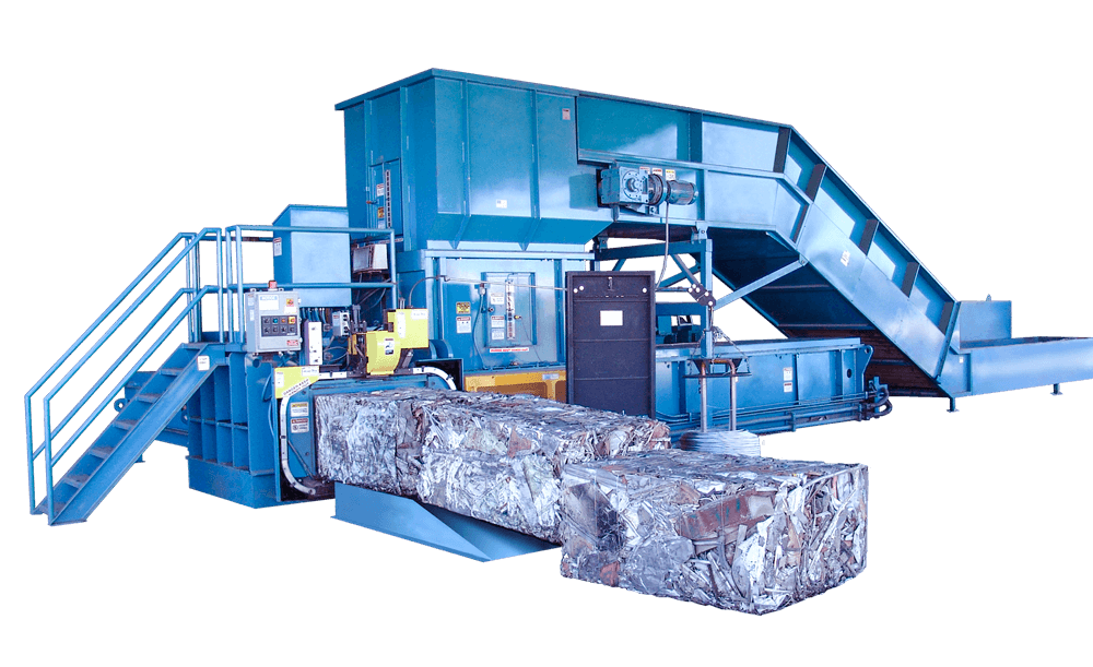
The two-ram baler is an excellent case study for understanding industrial automation, as it combines mechanical, electrical, and hydraulic systems under PLC control. Two-ram balers are widely used in recycling facilities to compress materials like paper, plastic, and metal into dense, manageable bales. The main cylinder applies high pressure to form the bale, while the secondary cylinder ejects it, allowing continuous operation. Coordinating these movements requires precise control to avoid collisions, which could damage the machine or halt production.
The PLC orchestrates this process by processing inputs from sensors and operator controls, then issuing commands to outputs like motor contactors and hydraulic valves. Photoelectric sensors, for instance, detect the position of each cylinder, ensuring the main cylinder is retracted before the secondary cylinder extends. Temperature sensors monitor hydraulic oil or motor conditions, alerting the PLC to potential overheating that could degrade performance or cause failures. Safety devices, such as door interlocks and emergency stops, are hardwired to ensure immediate shutdown if conditions become unsafe, bypassing the PLC for reliability.
For intermediate technicians, understanding the baler’s operation involves breaking down each step of the cycle. Start by mapping out the sequence: material loading, safety checks, compression, ejection, and reset. Each step depends on specific inputs and outputs, and the PLC must verify conditions before proceeding. Troubleshooting involves checking these components systematically. If the baler doesn’t start, verify the start button signal, safety interlocks, and PLC mode. If bales are inconsistent, inspect hydraulic pressure, sensor alignment, or timing settings. Regular maintenance, like checking hydraulic fluid levels and cleaning sensors, prevents issues and extends equipment life.
Additional Sections for Interested Technicians
PLC Programming Fundamentals
Programming a PLC for a two-ram baler requires understanding how to translate operational needs into logical instructions. The process begins with defining the system’s inputs and outputs, then creating a sequence that ensures safe and efficient operation. For example, the PLC must ensure the main cylinder completes its compression cycle before the secondary cylinder activates, using sensor feedback to confirm positions.
Technicians should start by sketching the operational sequence, noting each step and the conditions required to proceed. This might include checking that doors are closed, the start button is pressed, and both cylinders are retracted. The program then uses internal flags to track the cycle’s progress, moving from one stage to the next only when all conditions are met. Keeping the program simple and well-documented makes it easier to troubleshoot and modify later.
Testing the program is critical. Simulate inputs using a PLC simulator or test mode to verify that outputs activate correctly. For instance, pressing the start button should energize the motor contactor, but only if safety conditions are satisfied. Regular backups of the program are essential, as hardware failures or accidental overwrites can erase hours of work. Technicians should also document any changes, noting why they were made and how they affect the system.
Maintenance and Preventive Strategies
Maintaining a two-ram baler involves regular checks to ensure all components function correctly. Hydraulic systems require particular attention, as leaks or contaminated fluid can reduce efficiency or cause failures. Check fluid levels weekly, inspect hoses for wear, and replace filters as recommended by the manufacturer. Electrical components, like contactors and sensors, should be inspected for signs of overheating or corrosion, using tools like thermal cameras to detect hot spots.
Sensors, such as photoelectric or limit switches, must be kept clean and properly aligned to provide accurate feedback to the PLC. Misaligned sensors can cause the baler to misjudge cylinder positions, leading to collisions or incomplete cycles. Safety devices, including E-stops and door interlocks, should be tested monthly to ensure they interrupt power as intended. Keeping a maintenance log helps track these tasks and identify recurring issues.
Preventive strategies include scheduling downtime for thorough inspections, rather than waiting for breakdowns. For example, replacing worn hydraulic seals before they leak can save hours of cleanup and repair. Training operators to report unusual noises or performance issues early can also catch problems before they escalate, reducing downtime and repair costs.
Advanced Troubleshooting Techniques
When issues arise, a systematic approach is essential. Start by gathering information: what is the symptom, when did it start, and what changed recently? For example, if the baler stops mid-cycle, check the PLC’s status to see if it’s in run mode and review error codes. Next, inspect inputs like sensors and buttons, using a multimeter to confirm signals reach the PLC. If the issue is mechanical, such as a stuck cylinder, check hydraulic pressure and valve operation.
Common problems include sensor failures, wiring issues, or PLC program errors. For instance, a photoelectric sensor covered in dust might falsely indicate a cylinder’s position, halting the cycle. Cleaning or realigning the sensor can resolve this. Wiring issues, like loose connections or EMI from nearby motors, can disrupt signals, requiring shielded cables or rerouting. If the PLC program is suspected, review recent changes and compare the current program to a known backup.
For complex issues, collaborate with colleagues or consult manufacturer resources, such as Rockwell Automation’s Knowledgebase. Keeping detailed notes during troubleshooting helps build a reference for future problems, improving efficiency over time.
Safety Culture and Best Practices
Safety is the cornerstone of industrial automation. Beyond installing safety devices, technicians must foster a culture of safety awareness. This includes training operators to use E-stops correctly and ensuring maintenance tasks follow LOTO procedures. Never bypass safety devices, even temporarily, as this risks injury or equipment damage.
Best practices include labeling all components clearly, from wires to sensors, to reduce confusion during repairs. Maintain a clean workspace to prevent debris from interfering with sensors or hydraulics. Regularly review safety standards, such as OSHA guidelines, to ensure compliance. Encourage open communication between technicians and operators to catch issues early, creating a proactive environment that prioritizes both safety and performance.
PART 2: BALER GETS BALED
Okay, enough of the technical stuff. It's time to take all of that and turn it into real "on the job" knowledge. The best place I know to start is from the perspective of a two-ram baler operator starting their day. Every morning, as the sun peeks over the horizon(and sometimes before), the real work begins. You step into the plant, coffee in hand, and the first thing that hits you is the unmistakable scent of hydraulic fluid mixed with the faint aroma of dead animal. It’s a smell that tells you today is going to be a dance. You glance at the control panel, a mosaic of blinking lights and ominous warnings, and you can’t help but wonder which one will be your nemesis today.
Daily Startup – Or: "Why Is It Making That Noise?"
The morning ritual that separates professionals from those who will soon update their resumes:
-
Visual Inspection: Look for puddles of hydraulic fluid. If you find any, congratulations, you've discovered today's main task! Think like a mechanic checking a race car before the big event. Be thorough.
-
Check Fluid Levels: Hydraulic reservoir, lubrication points, and your own coffee cup – all must be adequately filled.
-
Clear Debris: Remove anything that might have fallen into the chamber overnight, including but not limited to: raccoons, mysterious metal objects, or the missing clipboard from last month.
-
Power Up Sequence:
-
Turn key to on position
-
Activate the Controls Start button. A horn should indicate this action
-
Start the pumps when baler is ready
-
Listen for the "normal" sounds (you'll learn to differentiate between "normal terrible" and "call the mechanic terrible")
-
Check pressure gauges – they should match the numbers written in Sharpie next to them by someone three technicians ago
-
Test Cycle: Run an empty cycle. If everything moves without sounding like a submarine imploding, proceed
Assuming you don't break anything, it's time to actually bale something. Now for the actual operation, the part where you convince tons of hydraulic pressure to do your bidding:
-
Material Loading: Your baler/compactor has dietary preferences. Feed it consistently. Overfeeding leads to jams; underfeeding leads to poorly formed bales and hurt feelings.
-
Compression Cycle: Once loaded, the baler initiates the compression cycle. The main ram will extend with all the grace of a rhinoceros doing ballet.
-
Auto vs. Manual Mode: Auto mode is for optimists. Manual mode is for realists. Choose according to your boss's philosophical outlook.
-
Bale Ejection (for balers): When your material is sufficiently tortured into a compact shape, the ejector ram will push it out like a mechanized birth.
-
Tie-off (for balers): If your machine has automatic tie-off, watch in amazement as it works correctly about 70% of the time. For manual tie-off, channel your inner boyscout and remember: the bale doesn't care about aesthetics.
When – not if – your baler/compactor decides to rebel, consult this glossary of common issues:
Problem: Hydraulic fluid creating an impromptu skating rink around the machine.
Diagnosis: Leak somewhere in the approximately 10,000 feet of hydraulic lines or one of the countless fittings.
Solution: Follow the wet trail to its source. Tighten fittings if possible. If a hose has ruptured, replace it while questioning every life decision that led you to this moment.
Problem: Main ram moves slower than a sloth on sedatives.
Diagnosis: Low hydraulic pressure, worn pump, or the machine's way of telling you it's Friday afternoon.
Solution: Check pressure settings, inspect relief valves, consider replacing the pump if it sounds like it's filled with gravel.
Problem: Control panel lights blinking in patterns that resemble alien communication.
Diagnosis: The rats have finally eaten through a wire.
Solution: Check connections, reset the system, and if that fails, call the one service company who won't call OSHA.
Problem: Unholy screeching during operation.
Diagnosis: Metal-on-metal contact where there should be lubrication.
Solution: Identify the unlubricated components and address immediately before something expensive happens.
Problem: Cross ram jams mid-extension.
Diagnosis: Material buildup, misalignment, or the machine testing your patience.
Solution: Clear obstructions, check alignment, and resist the urge to solve the problem with a sledgehammer.
Remember: Most problems can be solved by following the sacred troubleshooting trinity: Turn it off, wait, turn it on again. If that fails, then and only then should you consult the manufacturer's 1,000-page manual written by engineers who have clearly never had to repair their creation while covered in hydraulic fluid. Hopefully it doesn't get to that point because you're definitely going to keep up with regular maintenance, RIGHT? Regular maintenance is the difference between "managing a baler/compactor" and "being held hostage by a mechanical tyrant."
Daily Maintenance (Yes, Daily):
-
Wipe down sensors and photoeyes – they're like the machine's glasses, and they're always dirty
-
Check hydraulic connections – tighten anything weeping fluid
-
Remove debris from chambers and conveyor areas
-
Lubricate main bearing points (follow lubrication chart, or the crayon drawing left by your predecessor)
Weekly Maintenance:
-
Inspect shear blades for wear
-
Check tie system for wear and proper operation
-
Clean hydraulic coolers (unless you want your oil to reach the temperature of the sun's surface)
-
Inspect electrical connections while praying nothing arcs when you open the panel
Monthly Maintenance:
-
Change hydraulic filters (they're probably black with despair)
-
Check hydraulic fluid quality (if it looks like chocolate milk, you have water contamination)
-
Inspect ram guides and wear plates
-
Tighten all mounting bolts (physics and vibration conspire to loosen everything)
Annual Maintenance:
-
Change hydraulic fluid (an event worthy of taking before and after photos)
-
Inspect structural integrity (look for cracks, which are the machine's way of sighing)
-
Replace worn cylinders and seals
-
Update your will, because this job will be the death of you
Pro Tip: Create a maintenance log that's so detailed it would make a brain surgeon feel inadequate. When something catastrophically fails, you'll have proof you did everything possible to prevent the inevitable. You'll also start to notice patterns in your machine(s) and you'll start to speak their language. If you're a supervisor, spend time operating the baler. It's not going to get less scary and you're paying someone pennies to risk their neck out there anyways. Your baler/compactor has more ways to injure you than a horror movie villain. Respect it accordingly by training your crew on these practices. Sure, there's no true regulatory body until someone breaks their neck. How about no one breaks their neck? Here's some tips:
-
Lockout/Tagout: ALWAYS de-energize and lockout the machine before maintenance. The machine believes your fingers are just another material to be compacted, and your coworkers don't take a headcount every time they do something.
-
Never Bypass Safety Systems: Those interlocks and guards exist because someone before you learned a painful lesson. This is the most common bonehead move that I see on sites.
-
Confined Space Awareness: The inside of the baler is classified as a confined space. Never enter without proper procedures, permits, and a deep contemplation of your life choices.
-
Hydraulic Safety: High-pressure hydraulic fluid can inject into your skin without a visible wound. If you suspect a hydraulic injection injury, go to the emergency room immediately and enjoy explaining what a baler is to confused medical personnel. If you think it's no big deal then google it but don't click on the images. You've been warned.
-
Proper PPE: At minimum: safety glasses, steel-toed boots, gloves, and enough patience to endure the day. I opt for my PFGs whenever I can and I'll update readers when I lose a toe.
Remember: No bale is worth a trip to the emergency room, regardless of what your production-focused manager implies. Once you've mastered the basics and retained all your appendages for at least six months, you're ready for advanced techniques:
Material Mixing Mastery: Different materials compact differently. Learn the perfect "recipe" of materials for optimal density. It's like cooking, if your cookbook could hydraulically crush you.
Seasonal Adjustments: Your baler/compactor behaves differently in different temperatures. Summer means overheating concerns; winter means cold hydraulic fluid and sluggish movement. Adjust accordingly; leave your heater on overnight in the winter. If you don't know how then ask your supervisor. If you're the supervisor then go rub your hands on the hydraulic tank vigorously while you wait for the service technician to show up and tell you whether or not you have a functioning heater.
Pressure Customization: Factory settings are a starting point, not gospel. Learn to safely adjust pressures for different materials and conditions. IQ TEST REQUIRED
The "Whisper Technique": Experienced operators claim they can hear problems before any warning lights appear. Develop this sixth sense by spending unhealthy amounts of time listening to your machine. You see all of those dancing lights on the front of the 'puter? Every single one means something.
After months of operation, you'll experience a shift in perspective. What once was an intimidating hydraulic monster becomes an extension of your will. You'll develop a bizarre appreciation for well-formed bales. You'll take pride in tonnage reports. You'll find yourself explaining the intricacies of compaction physics at parties, while people slowly back away.
Embrace this transformation. You've joined an exclusive club of individuals who transform chaos into order, who convert loose materials into tidy packages, who have a history of saying "that guy doesn't work here anymore".
Your baler/compactor isn't just a machine; it's a philosophy made manifest in steel and hydraulic fluid. It teaches patience, respect, and the transient nature of machinery that works properly. For us, it's not generating profit. It's not actually about tonnage or bales per day. It's not about corporate C-suite wellness retreats and quarterly bonuses, or $1500 production bonuses for a "production manager" who makes 50k per year. For us, it's just a job. It's what we do to make money. If we're already going to do it for money then we might as well figure out how to extract more money. I'm not interested in management or office work, but I'm also not interested in getting paid like shit to do shit work for someone who enjoys treating people like shit. My only way out is through technology. Find your own drive and your own perspective and you'll easily find a way to make more money with these monstrosities.
When a technician shows up to your site, there's a good chance that he is not interested in anything I just said. He's going to grunt and groan until the job is done and that's it. When he shows up on your site, follow this as a guideline to ensure a prompt and easy service. Too many operators cause issues and then shrug for 5 hours while no one can find the issue. Just speak up and we will all move on with our lives. I'm on T&M anyways. Here's some tips on this one:
-
Be honest about the machine's quirks. That weird noise it makes when the temperature drops below 40°F? They need to know that's normal.
-
Share the unofficial solutions you've discovered. The specific way you have to jiggle the control panel when it freezes? That's valuable institutional knowledge.
-
Warn them about That One Maintenance Task that always takes three times longer than it should.
-
Remind them that despite all its flaws, when this machine is running properly, it's an industrial marvel.
Most importantly, pass along this guide, now enhanced with your own brainwaves and blood stains. The wisdom must continue.
END OF TRANSMISSION